Brilliance
| About the project | |||||||||||||||||||||||||||||||||||||||||||||||||||||||||||||||||||||||||||||||||||||||||||||||||||||||||
|
Brilliance is a 4WD (4-Wheel Drive) robot development platform powered by an ATmega 644P microcontroller, mounted on a custom AVR development board.
The development board can also be used independently for embedded applications, including high-speed wireless communication (SPI, I2C, UART), human-computer interaction, sensor integration, motor control, and more. |
|||||||||||||||||||||||||||||||||||||||||||||||||||||||||||||||||||||||||||||||||||||||||||||||||||||||||
What's so special? | |||||||||||||||||||||||||||||||||||||||||||||||||||||||||||||||||||||||||||||||||||||||||||||||||||||||||
|
The development board is fully compatible with the open source prototyping platform Arduino. You can use most of the popular Atmel's microcontrollers* with Arduino bootloader burned on it.
Additionally, you can both stack any Arduino shield on it and use this board as a shield on top of an existing Arduino stack by soldering male/female header pins on the appropriate sides. |
|||||||||||||||||||||||||||||||||||||||||||||||||||||||||||||||||||||||||||||||||||||||||||||||||||||||||
The Board : | |||||||||||||||||||||||||||||||||||||||||||||||||||||||||||||||||||||||||||||||||||||||||||||||||||||||||
| It was built using EasyEDA. Unfortunately, I lost all the design files of this board. long story(thanks to Google) | |||||||||||||||||||||||||||||||||||||||||||||||||||||||||||||||||||||||||||||||||||||||||||||||||||||||||
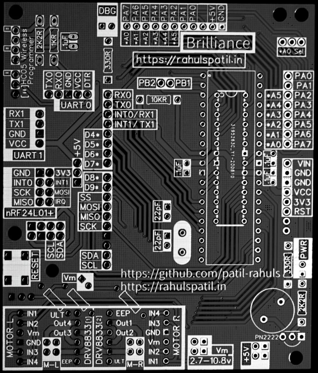
1. Brilliance Development Board - Front 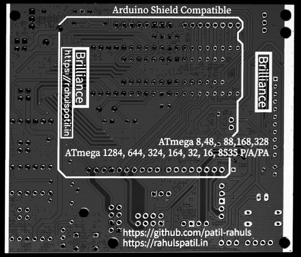
2. Brilliance Development Board - Rear |
|||||||||||||||||||||||||||||||||||||||||||||||||||||||||||||||||||||||||||||||||||||||||||||||||||||||||
Features & Specifications | |||||||||||||||||||||||||||||||||||||||||||||||||||||||||||||||||||||||||||||||||||||||||||||||||||||||||
|
2 x DRV8833 Motor Drivers - for driving two brushed DC/Servo motors. Each DRV8833 Motor driver is in parellel configuration to provide maximum output current per motor (2.4 A).
Active Buzzer - connected to Digital pin 03. Connection (Headers) for 0.96" OLED Displays. Bluetooth communication Headers for connecting HC-06 and HC-05 Modules. Connection headers for NRF Modules (SPI). Connection headers for Wireless Serial Modules like HC-12. |
|||||||||||||||||||||||||||||||||||||||||||||||||||||||||||||||||||||||||||||||||||||||||||||||||||||||||
Pin Mapping | |||||||||||||||||||||||||||||||||||||||||||||||||||||||||||||||||||||||||||||||||||||||||||||||||||||||||
| |||||||||||||||||||||||||||||||||||||||||||||||||||||||||||||||||||||||||||||||||||||||||||||||||||||||||
Main Parts | |||||||||||||||||||||||||||||||||||||||||||||||||||||||||||||||||||||||||||||||||||||||||||||||||||||||||
|
- Low level controller - AtMega644P Microcontroller.
- Processing - Android device can be connected to the controller adding to the system's processing power. | |||||||||||||||||||||||||||||||||||||||||||||||||||||||||||||||||||||||||||||||||||||||||||||||||||||||||
| | |||||||||||||||||||||||||||||||||||||||||||||||||||||||||||||||||||||||||||||||||||||||||||||||||||||||||
| | |||||||||||||||||||||||||||||||||||||||||||||||||||||||||||||||||||||||||||||||||||||||||||||||||||||||||